
GBT IF system#
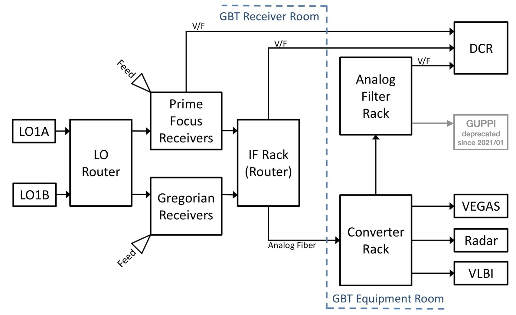
This is a simplified flow diagram of the GBT IF system routing
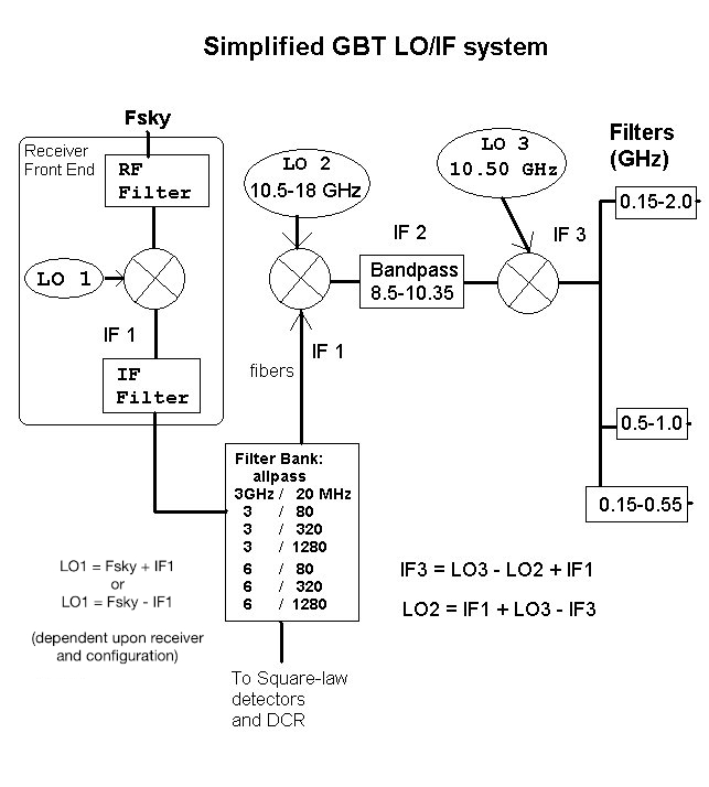
This is a simplified flow chart of the GBT IF system
Note
MUSTANG-2 is not covered in those figures, since it is a direct detection system.
During each frequency mix, each polarization pair is mixed with a signal from the same synthesizer. All synthesizers are locked to our H-maser frequency standard.
From the Receiver to the IF Rack#
The frequency that is observed is given by \(F_{\text{sky}}\). Within the receiver the detected signal at \(F_{\text{sky}}\) is mixed with the LO1 signal. The LO1 frequency is derived from a synthesizer and can vary in time when Doppler tracking the velocity of a spectral line. The result of the mixing of \(F_{\text{sky}}\) and LO1 is the IF frequency, IF1. The typical IF1 center frequencies are 1080, 3000 and 6000 MHz. Filters limit the bandwidth in the receivers both before and after the LO1 mix. There are also filters in the IF rack that limit the bandwidth. The resulting allowed bandwidths are 20, 80, 320, 1280 MHz and “All Pass”, i.e. no filtering other than the response of the receiver.
Before the IF Rack each signal is split into two (single beam receivers only) copies of the original signal. Each signal in the IF Rack is detected and then sent to the DCR (as used during pointing and focus observations). Each signal is also sent as an analog signal over optical fiber to the Jansky Lab to the Converter Rack.
From the Converter Rack to the Backend#
When the signal reaches the Converter Rack it is split into four separate copies. This allows up to eight different copies of the received signal for single beam receivers and four copies of each received signal for dual beam receivers.
In the Converter Rack the signal is mixed with the LO2 signal. Each copy of the signal can be mixed with a different LO2 since there are eight different LO2 synthesizers. The resultant signals are then sent through a filter to make sure it has a bandpass of no more than 1.85 GHz. A final mix with a fixed frequency of 10.5 GHz then gets the signal within the input band-passes of the backends. There is a final set of filters that ensures the signal has the correct bandwidth for the backend.
KFPA Combined IF#
The KFPA receiver, with 7 beams, is the first GBT receiver with more IF signals than there are optical fibers from the GBT to the Jansky Lab. In order to bring the IF signals to the control room, pairs of signals from different beams were duplexed on single fibers. The signal combination was accomplished by an analog addition of the IF of pairs of beams. Beams 1, 2, 3 and 4 have IF signals centers at 6800 MHz. The IF signals from beams 5, 6 and 7 are down converted to 2100 MHz center frequency. Beam 2 is paired with 6, beam 3 with 7 and beam 4 with 5. The next image shows the combination of KFPA beams onto fiber modems and their selection in the Converter Rack Modules A and B:
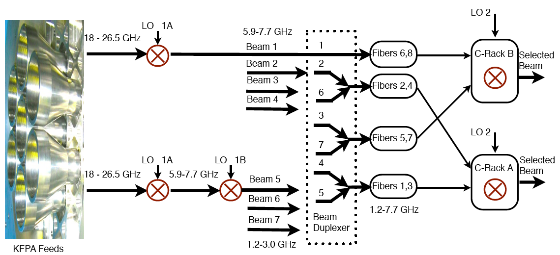
At the Converter Rack one of the two beams is selected by appropriately setting the converter rack LO frequency. Beams 2, 4, 5 and 6 are routed to Converter Rack A and beams 1, 3 and 7 to Converter Rack B. This constrains certain multi-beam observing modes, as is described in K-Band Focal Plane Array (KFPA).